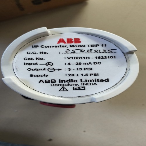
About ABB Make IP Converter ( TEIP11 )
The TEIP11 signal converter converts standard electrical signals, e.g. 4 to 20 mA to 0.2 to 1 bar (3 to 15 psi). It is therefore a connecting link between electrical/electronic and pneumatic systems. The signal conversion process is similar to the patented force balance method. Special features of the TEIP11 signal converter are its relatively small dimensions and outstanding operational stability when subject to shock and vibration. The converter can be subjected to loads up to 10 g with less than 1% effect on function. The housing units are available in a variety of models to meet your installation requirements. For potentially explosive conditions, units that offer intrinsically safe operation or pressure-resistant encapsulation are available with international approval certificates for use worldwide. Various ranges can be supplied on the input side and the output side for signal conversion (see Specification on page 4). The device requires only compressed air 1.4 to 10 bar (20 to 145 psi) for the power supply. In order to ensure smaller dimensions and lower costs, an air power stage is not included in the pneumatic unit. This reduces the air capacity, meaning that the I/P signal converter can only be used to control small-volume air systems.
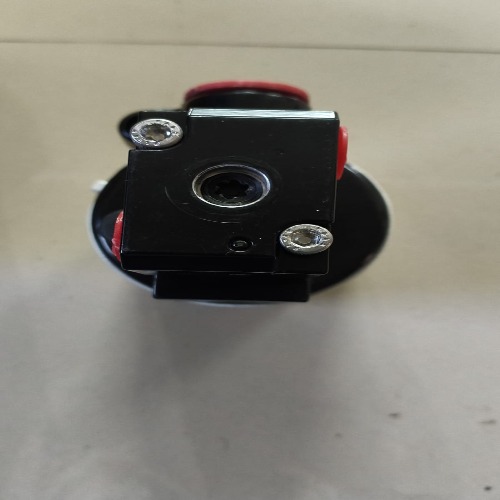
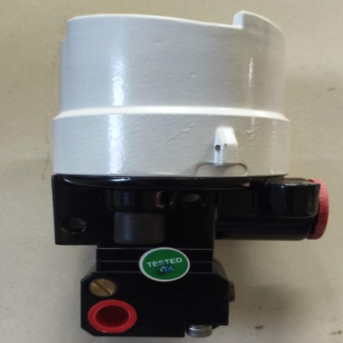
Control room housing unit for rail mounting The control room housing for rail mounting is the simplest and lowest priced version of the I/P signal converter. A mounting base that is compatible with all commercially available EN rails is used for installation. The housing unit with plastic cap has an IP 20 protection rating. Field mount housing The field mount housing is suited for installation on-site or in open areas. The housing can be made from plastic with IP rating IP 54, from aluminum with IP rating IP 65 and from stainless steel with IP rating IP 65. The housing is suited for wall mounting and for 2 in pipe mounting
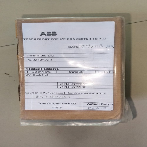
Specification Input (electric) Signal range 0 to 20 mA or 4 to 20 mA 0 to 10 mA or 10 to 20 mA 4 to 12 mA or 12 to 20 mA (additional ranges available upon request) Input resistance Ri = 260 at 20 C (68 F), Tk + 0.4 %/K Overpressure limit 30 mA (for Ex devices see ). Capacitance / inductance Negligible
Output (pneumatic) Signal range 0.2 to 1 bar (3 to 15 psi)
Air capacity at supply air pressure [kg/h] [Nm3/h] [scfm] 1.4 bar (20 psi) 0.05 0.041 0.024 2.0 bar (30 psi) 0.07 0.057 0.033 4.0 bar (60 psi) 0.10 0.082 0.048 6.0 bar (90 psi) 0.16 0.130 0.076 10.0 bar(150 psi) 0.25 0.205 0.120
Specification Design for field housing unit (aluminum/stainless steel) Material / IP rating IP 65 aluminum or stainless steel housing unit Surface Aluminum housing, painted with dual component coating, lower section, black, RAL 9005, screw-on cover, Pantone 420, stainless steel housing unit, electrolytically polished Mounting Wall or 2 in pipe mounting With stainless steel mounting bracket (accessory) Electrical connection 2-pole screw terminal for 2.5 mm2 (14 AWG) in the housing, screw connection NPT in for the cable entry. For ATEX intrinsically safe: Threaded hole NPT in for the cable entry For ATEX Ex d: M20 1.5 threaded hole for cable entry at FM/CSA (Cable gland with Ex d approval available as an accessory


 Send Inquiry

 Send Inquiry
 Send SMS